All modern automotive engines feature an engine control unit (ECU), which is a device for controlling emissions, performance, and efficiency. An ECU is activated through a number of sensors within an engine that constantly monitor it within set parameters and, from the information obtained, the ECU conditions the engine to control certain variables, such as amount of fuel sent into the engine and when to start it.
Many automotive companies strive to employ an ECU that could ensure that the engine would run to its full potential. Some ECUs feature different engine mappings, making it possible to switch from ‘economy mode’ to ‘sport mode’, thus switching from a fuel-efficient mode to a more powerful performance. However, certain functions could only be achieved in conjunction with an ECU. One example is the Volkswagen active-cylinder technology (ACT), which is designed to automatically stop the fuel supply to two of the engine cylinders when carrying a lighter load, in order to save fuel. Such functions make it possible to continue producing higher-performance engines, paying due attention to environmental obligations, by providing an optimal balance between performance, fuel economy and lower emissions.
This project consists of developing the hardware for an ECU based on a Genesys Virtex 5 FPGA platform, together with the necessary electronic interfaces required for monitoring sensors and driving actuators. The programming was carried out using the hardware-description language VHDL in order to define the digital module used to process the information received from sensors, and outputting the signals to the engine components. The electronic circuitry was employed to interface the crank position sensor, MAP
sensor, and spark plugs, and for driving the injectors. The TLP250 optocoupler was especially used to isolate and protect the FPGA (field-programmable gate array) from potentially dangerous voltages, as well as to drive higher- voltage components.
In order to implement and test the system safely, each module was built and tested separately. Components such as the injector, spark plug, and CPS modules were built and tested with hard-coded HDL blocks. Once their operation was confirmed, they were connected to their pertaining PMOD ports and circuit blocks, and tested again with an oscilloscope to confirm the voltage output. The timing of these components was also tested with a number of output flags to confirm that the various signals were switching on at the right time, and for the right length of time.
The final product contained three main hardware components, namely: an FPGA, a breadboard circuit for the interface electronics, and the several actuators and sensors on the vehicle itself. Each of these vehicle components was tested from the circuit output and FPGA, and it was confirmed that the FPGA could properly drive the multiple actuators and detect all of the sensors. Since accuracy was a major consideration in the project, it was necessary to test the timing constraints thoroughly. To this end, the clock speed of the FPGA was set to 10 nanoseconds and the timing accuracy was to 10 nanoseconds. This was deemed highly satisfactory, and in excess of what would be required from an automotive engine. All the basic functions were tested and confirmed to work properly with the given timing constraints down to the 10- nanosecond clock.
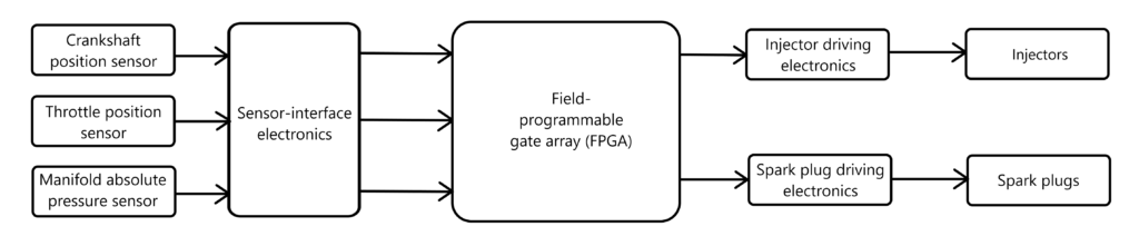
Figure 1. Block diagram of the system and actual implementation
Student: Andrew Muscat
Course: B.Sc. IT (Hons.) Computer Engineering
Supervisor: Prof. Ivan Grech
Co-supervisor: Prof. Mario Farrugia