The translation of natural-language specifications to model- based specification could be defined as the translation from unstructured to structured-system specification. In this step, there is always the possibility of the presence of translation errors, such as human errors, which arise from unstructured text analysis [1,2]. This project aims to explore and study this translation process, with a view to propose an automated mapping paradigm to produce structured models from unstructured natural textual descriptions of system behaviour.

After substantial research on both unstructured and structured languages, the project focused on the translation of natural language to Unified Modeling Language (UML), a graphical language that includes various non-mathematical software-modelling techniques, each aimed at visualising, specifying, constructing, and documenting software systems [3]. The transformation was carried out through two main steps: analysis and data extraction from natural language, and mapping the analysed text to a specific formalised model notation.
The first stage includes the synthetic reconstruction of the specification text and various natural-processing techniques. Sentence segmentation, tokenisation, lemmatisation, parts of speech tagging and named-entity recognition all played a part in the text-normalisation displayed in Figure 1. Through this process, the ambiguity, inconsistency and incompleteness of natural language are tackled, producing a standard format that was sufficiently adequate to act as an input for the mapping paradigm.
The mapping paradigm involves a series of rules and patterns directed towards identifying the components of the UML models. This project concentrates on the development of use-case diagrams, which are directed towards system- client interaction and highlighting system functionalities, and class diagrams, which provide visual schematics of the system that assist its design and implementation [3]. Elements and their relationships could be identified by using the first-stage output against the mapping paradigm. Through this step, a visual representation of the diagram is presented to the user.
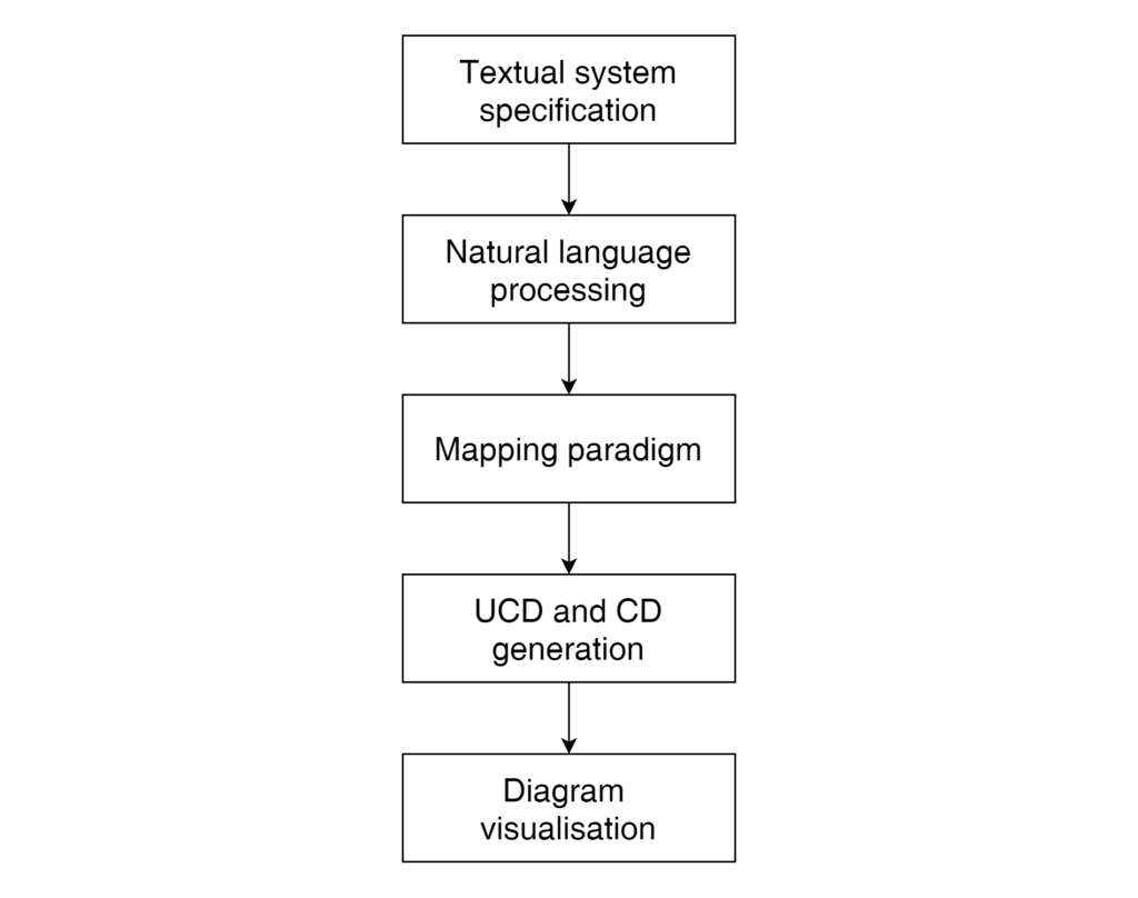
The proposed fully automated system, as illustrated in Figure 2, provides the developer with a tool that could create diagrams with accuracy and ease, facilitated with optional manual refinement, thus being of help in the validation and verification of the system. This improves the system analysis by the client and the development team through the detection of errors prior to development. Thus, any risk could be better pre-empted and averted, making the development life cycle process more efficient, in terms of time and cost [4].
References/Bibliography:
[1] M. Leszek A and B. L. Liong, Practical Software Engineering. UK: Addison-Wesley, 2005.
[2] M. Muqeem and M. Rizwan, “Validation of Requirement Elicitation Framework using Machine,” in IEEE International Conference on Control, Instrumentation, Communication and Computational Technologies (ICCICCT), 2014, pp. 1210–1216, doi: 10.1109/ ICCICCT.2014.6993145.
[3] Unified Modeling Language, 2.5.1. Object Management Group, 2017.
[4] S. Kumar, R. Singh Suryavanshi, and G. Chandra, “Formal Methods:Techniques and Languages For Software Development,” 2015.
Student: Jonathan Zammit
Course: B.Sc. IT (Hons.) Software Development
Supervisor: Prof. Ernest Cachia