Implementing real-time digital signal processing could be computationally expensive when developed as software to be run on a generic computer platform. A solution to compensate for the high computational demand would be to implement it as an application-specific hardware. This could be achieved in various ways, one of which being through field-programmable gate array (FPGA), which permits an inherent parallelised architecture that facilitates real-time processing.
The aim of this project was to develop and implement different digital audio effects, using a hardware definition language. In particular, this work presents the implementation of a guitar-effects pedal board, based on an FPGA. A block diagram representation of the implemented system is shown in Figure 1. The Atlys Spartan-6 FPGA trainer board was used since it features an AC-97 audio codec with line-in/line-out, microphone and headphone interfaces, which facilitated the implementation. A number of effects were introduced, including: echo, reverb, chorus, distortion, tremolo, phaser and flanging. The implementation of these effects was aided by considering the Z-transform transfer function of each effect. The implementation was designed around the AC-97 audio-codec hardware driver developed by Tony Storey, and obtained from Digi-Key. This driver runs at a 48 kHz sampling rate and features an 18- bit signal representation. An analogue signal-conditioning amplifier, based on an OPA 350 operational amplifier, was also designed and implemented on a printed circuit board to adequately amplify the signal from an electrical guitar prior to feeding it into to the ADC of FPGA trainer board. It is to be noted that the AC-97 audio codec has its own frequency-dependent phase-shift contribution which had to be taken into consideration while carrying out the various tests.
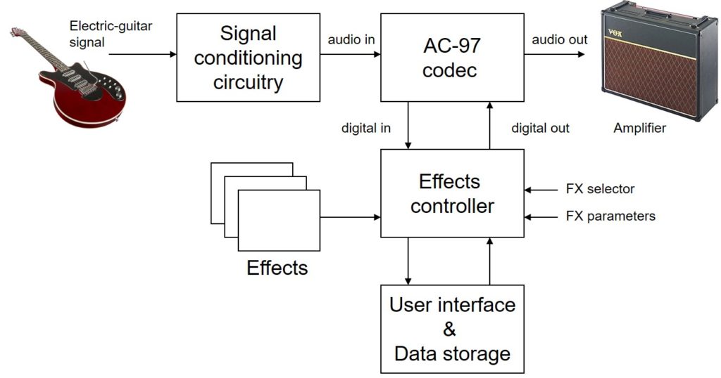
The selected effect was applied to the raw digitised signal, which was eventually converted to the analogue domain through the on-board DAC, and outputted to an amplified speaker. The performance of the implemented system was tested and verified while comparing the measured results with those obtained from the ideal implementations carried out in MATLAB. Depending on the nature of the effect, the frequency response and/or the transient response of each effect was verified by means of a high-speed digital oscilloscope and a signal generator, as shown in Figure 2.
Student: Peter Galea St. John
Course: B.Sc. IT (Hons.) Computer Engineering
Supervisor: Dr. Ing. Owen Casha